PERKO, Inc.
16490 N.W. 13th Ave
Miami, FL 33169-5707
www.perko.com
Fig. 0525 Locking Insert for Fuel Fills
INSTRUCTIONS FOR USE
IMPORTANT:
Since a key is not required to insert the locking insert, it is important that the key and
device match by operating the lock (retracting the cams) prior to inserting the device for the first
time. Also on older fills, before inserting the lock, check for a ridge around the top of the fill neck and
remove with a pen knife if present. If the top of the fill neck does not make a smooth transition to the upper
part of the fill, the locking insert will be difficult to insert and more difficult to remove. See diagram 1 below.
1. This device is designed to be used (as supplied) on PERKO
®
brand fills models 0540, 0541, 0580,
0581, 0582, 0583, 0590, 0591, 1318, and 1319. Note: This device is not to be used as a high
security device.
2. This device can be used on PERKO
®
brand fills models 0542 and 0543 if the plastic cap retainer
system is abandoned. See Instruction #5.
3. To install into a compatible deck fill, press the device (key slot side up) into the throat of the fill. Spring
action will retract the cams, which will expand and lock onto the hose bib of the fill when the device is
fully inserted. On 0540 through 0591 models, the tab on the top of the device should be
orientated to fall into the vent opening notch in the fill’s throat. This prevents rotation when the device
is removed.
4. To remove the device, insert key and turn counterclockwise 90 degrees. This will retract the locking
cams, not allowing the key to be removed, and thus allowing the removal of the insert from the fill by
using the key as a handle pull. On 1318 and 1319 fills, place a finger on the top of the device, using
one of the two ribs on the top to prevent rotation of the device while the key is rotated counter-
clockwise.
5. To make model 0542 and 0543 fills compatible, the plastic cap retainer system must be removed.
To do this:
a. Locate the small rectangular loop in the fill neck that retains the end of the plastic retainer strap.
b. Using a plastic handled flat screwdriver and small hammer, place the blade of the screw
driver on one of the sides of the rectangular loop. Lightly strike the screwdriver to shear
one side of the rectangle loop off of the throat of the fill. Strike hammer to the plastic
handle of the screwdriver only.
c. Remove the strap from the open loop, then remove the strap from the cap and discard
the strap.
d. Using a pair of pliers, tear the remainder of the rectangular loop from the throat of the
fill and discard.
WARNING: Do not strike any metal with a hammer
while fuel cap is removed. A spark could result and
ignite the fuel vapors causing serious injury or death.
PERKO
Fig. 0580
& 0582
PERKO
Fig. 0581
& 0583
PERKO
Fig. 0542
& 0543
PERKO
Fig. 1318
PERKO
Fig. 1319
U.S. Marine
PN: 72502
Made by PERKO
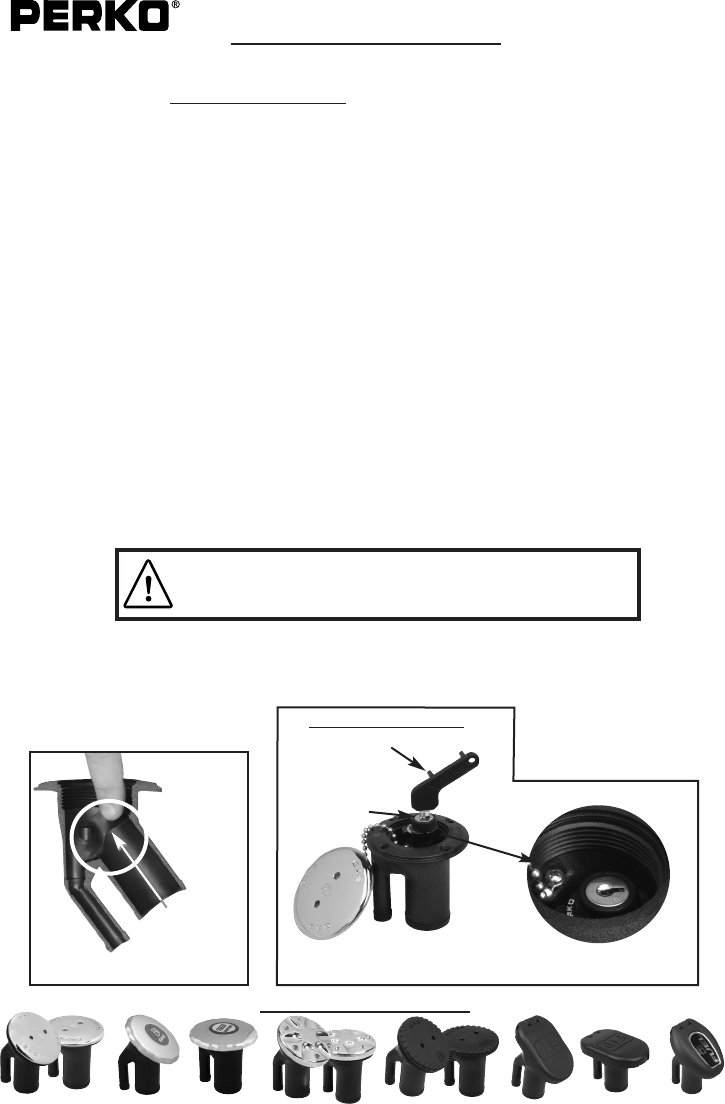
Compatible Fuel Fills
Illustration of Locking Insert in Fuel Fill
Dual Purpose Key
Opens Fill Cap
Operates Lock
Cylinder
PATENT NO.
US D512,300 S
05/08
0525INS1
PERKO
Fig. 0540 &
0541
PERKO
Fig. 0590
& 0591
Diagram 1
Check for
ridge with finger.
If present trim with
pocket knife
PERKO, Inc.
16490 N.W. 13th Ave
Miami, FL 33169-5707
www.perko.com
Fig. 0525 Locking Insert for Fuel Fills
INSTRUCTIONS FOR USE
IMPORTANT:
Since a key is not required to insert the locking insert, it is important that the key and
device match by operating the lock (retracting the cams) prior to inserting the device for the first
time. Also on older fills, before inserting the lock, check for a ridge around the top of the fill neck and
remove with a pen knife if present. If the top of the fill neck does not make a smooth transition to the upper
part of the fill, the locking insert will be difficult to insert and more difficult to remove. See diagram 1 below.
1. This device is designed to be used (as supplied) on PERKO
®
brand fills models 0540, 0541, 0580,
0581, 0582, 0583, 0590, 0591, 1318, and 1319. Note: This device is not to be used as a high
security device.
2. This device can be used on PERKO
®
brand fills models 0542 and 0543 if the plastic cap retainer
system is abandoned. See Instruction #5.
3. To install into a compatible deck fill, press the device (key slot side up) into the throat of the fill. Spring
action will retract the cams, which will expand and lock onto the hose bib of the fill when the device is
fully inserted. On 0540 through 0591 models, the tab on the top of the device should be
orientated to fall into the vent opening notch in the fill’s throat. This prevents rotation when the device
is removed.
4. To remove the device, insert key and turn counterclockwise 90 degrees. This will retract the locking
cams, not allowing the key to be removed, and thus allowing the removal of the insert from the fill by
using the key as a handle pull. On 1318 and 1319 fills, place a finger on the top of the device, using
one of the two ribs on the top to prevent rotation of the device while the key is rotated counter-
clockwise.
5. To make model 0542 and 0543 fills compatible, the plastic cap retainer system must be removed.
To do this:
a. Locate the small rectangular loop in the fill neck that retains the end of the plastic retainer strap.
b. Using a plastic handled flat screwdriver and small hammer, place the blade of the screw
driver on one of the sides of the rectangular loop. Lightly strike the screwdriver to shear
one side of the rectangle loop off of the throat of the fill. Strike hammer to the plastic
handle of the screwdriver only.
c. Remove the strap from the open loop, then remove the strap from the cap and discard
the strap.
d. Using a pair of pliers, tear the remainder of the rectangular loop from the throat of the
fill and discard.
WARNING: Do not strike any metal with a hammer
while fuel cap is removed. A spark could result and
ignite the fuel vapors causing serious injury or death.
PERKO
Fig. 0580
& 0582
PERKO
Fig. 0581
& 0583
PERKO
Fig. 0542
& 0543
PERKO
Fig. 1318
PERKO
Fig. 1319
U.S. Marine
PN: 72502
Made by PERKO
Compatible Fuel Fills
Illustration of Locking Insert in Fuel Fill
Dual Purpose Key
Opens Fill Cap
Operates Lock
Cylinder
PATENT NO.
US D512,300 S
05/08
0525INS1
PERKO
Fig. 0540 &
0541
PERKO
Fig. 0590
& 0591
Diagram 1
Check for
ridge with finger.
If present trim with
pocket knife
 (1 pages)
 Manymanuals.com
 Manymanuals.de
 Manymanuals.fr
 Manymanuals.it
 Manymanuals.pl
 Manymanuals.cz
 Manymanuals.es
 Manymanuals-pt.com
Commentaires sur ces manuels